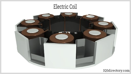
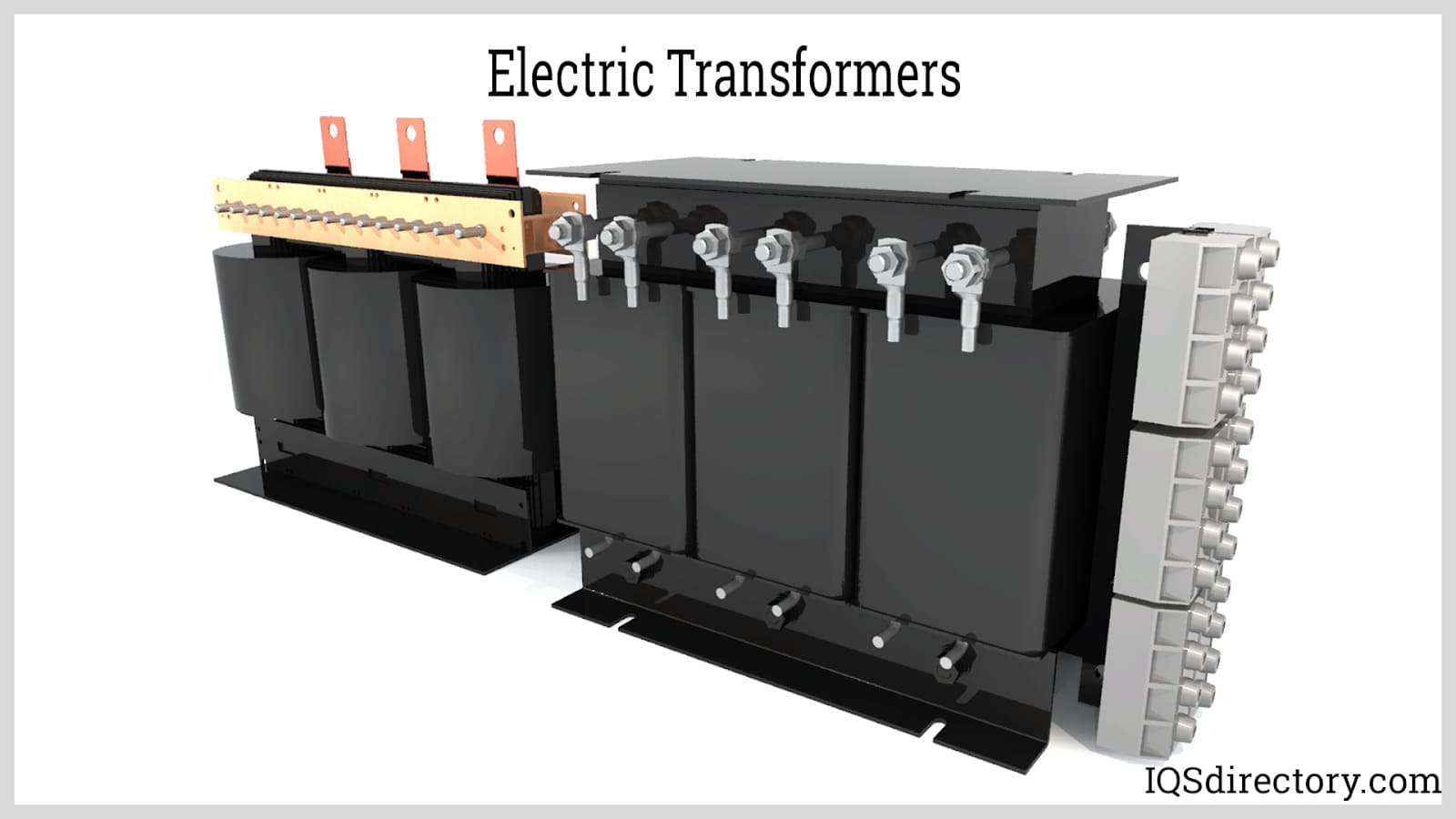
An induction coil electrical transformer converts a low-voltage direct current (DC) supply into high-voltage pulses. An induction coil converts energy from an electric current into a magnetic field or the other way around by storing it as a magnetic field in the core. By continuously interrupting the direct current in the primary coil with a vibrating mechanical contact known as an interrupter, the direct current can modify the flux to induce the voltage in the secondary coil. Read More…
We are proud of the craftsmanship of our engineers. All of our products are made right here in the United States and we promise that these items are created from high quality resources. Our electrical coils are unique and efficient.

Established in 1973, Classic Coil Company is a Contract Manufacturer of electronic coils. We manufacture coils for a variety of industries; winding wire gauges from 4-58 AWG. We are ISO 9001-2015 certified, ITAR registered and DFARS Compliant. Our Engineering services allow us to assist with design, reduce cost, and increase efficiency in production. Call or visit our website to learn more about...

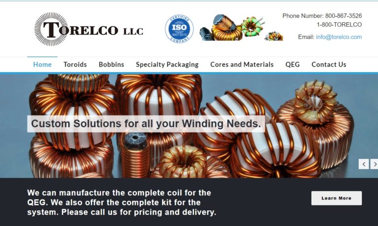
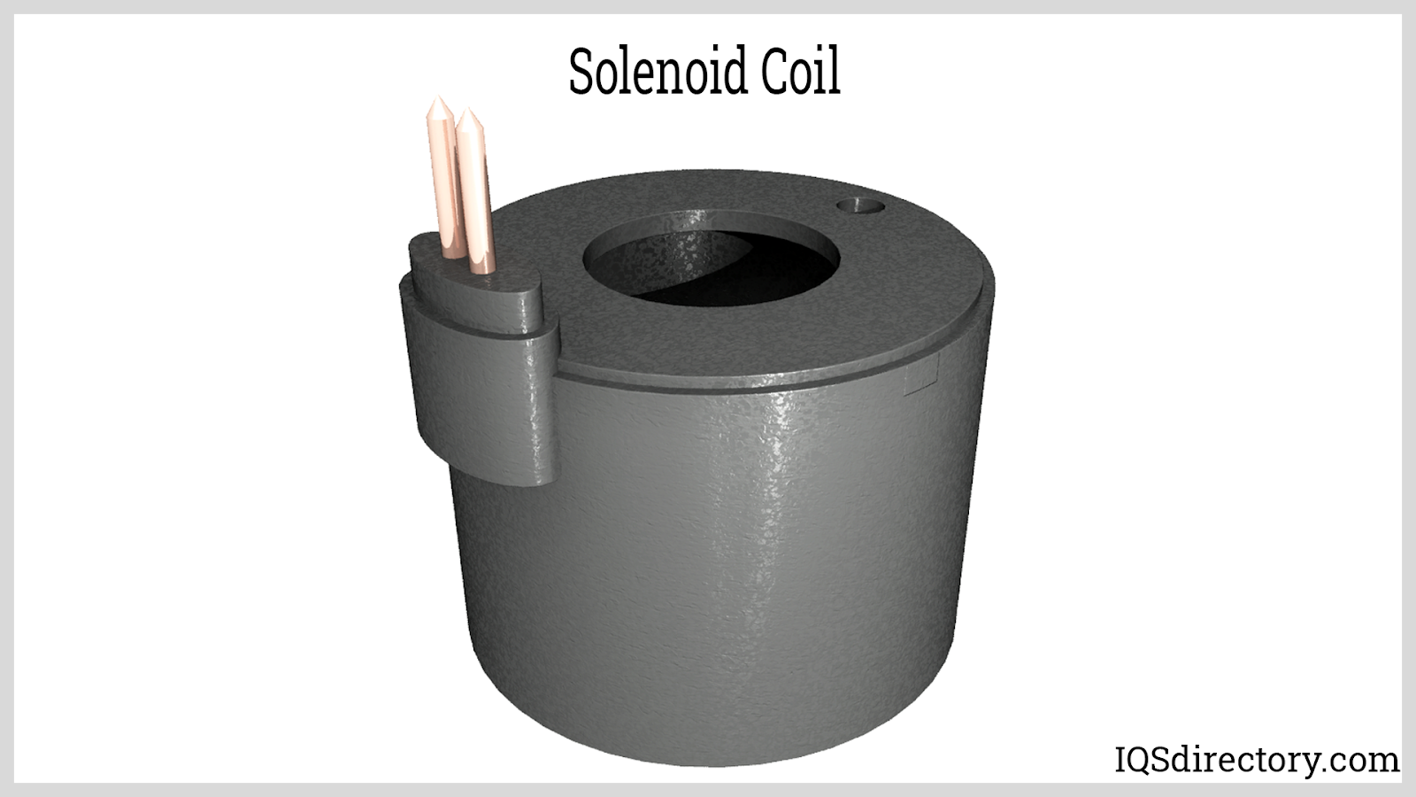
Since 1962, Torelco has been a supplier of electric coils and transformers of superior quality. We offer custom coils, solenoid coils, ferrite core coils & toroid wound coils to serve a range of industries. Markets served include medical, military, electronics, and industrial. When you work with us, our promise is to build to the exact specifications and meet the custom needs of our customers.
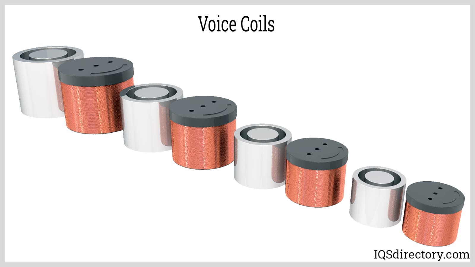
Check out what’s new online at Precision Econowind, manufacturer of the highest quality custom coils at reasonable prices, with on time delivery. Serving the coil industry for over 30 years, we’re experienced with producing loudspeaker & medical industry coils, coils wound on customers’ bobbins/tooling; freestanding, flat wire, edge wound, square, rectangle & shaped coils. Submit your specs ...

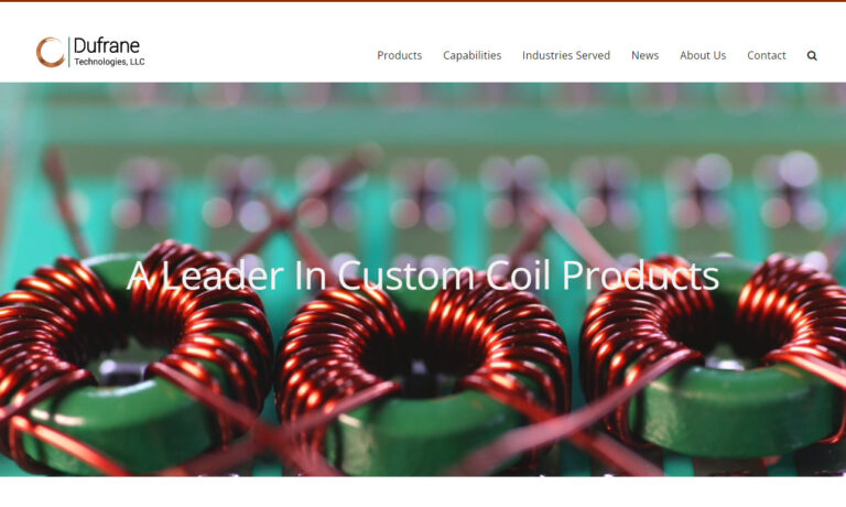
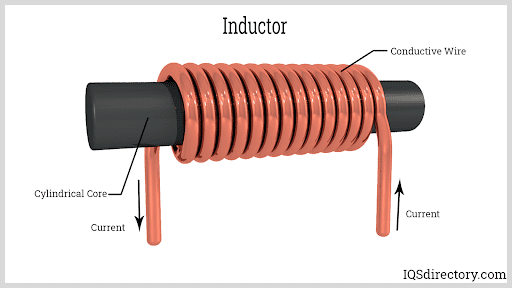
An inductor is a two-terminal electrical component that stores energy in a magnetic field when electric current flows through it. An inductor typically consists of an insulated wire wound into a coil. Inductors have only one coil. Usually – it’s accepted that a choke is an inductor which carries DC, while a reactor is an inductor which carries AC. Dufrane designs and manufacture inductors, ...
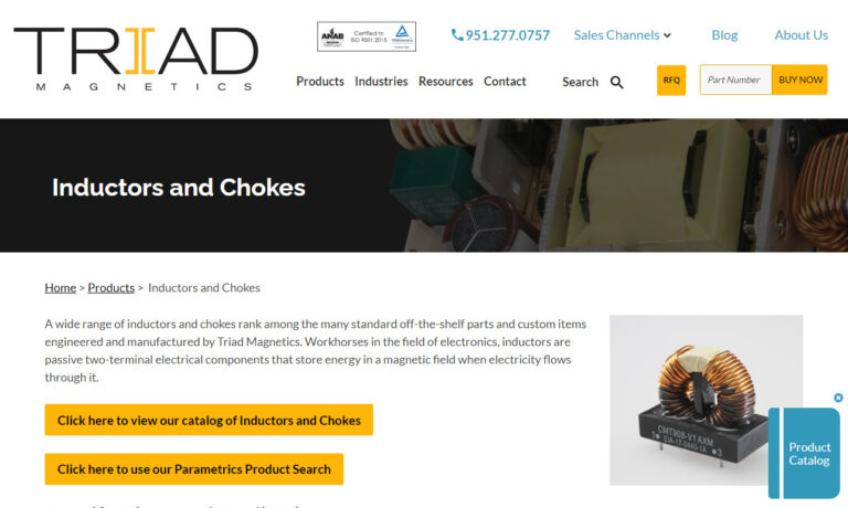
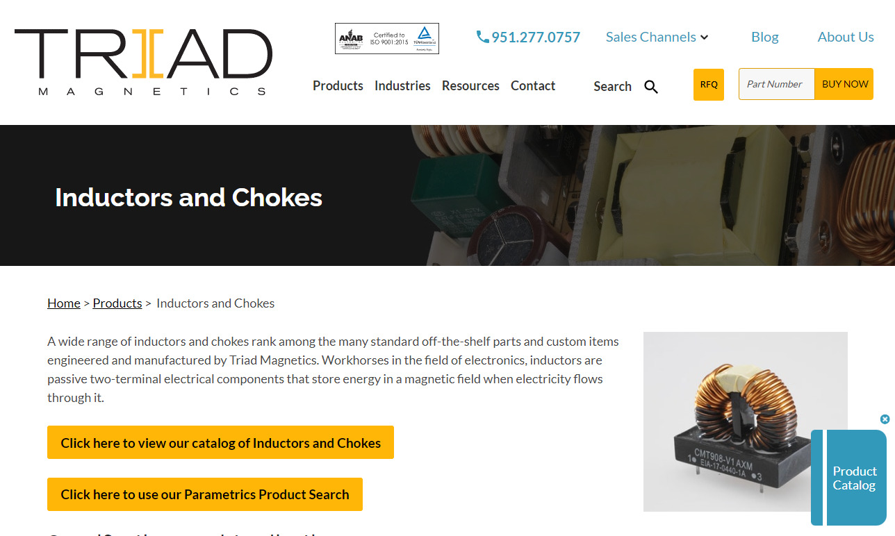
Triad Magnetics has been in the electric coils industry for over 75 years. Giving us the knowledge and expertise to be one of the best in the industry. We have a wide range of electric coils and inductors as well as the ability to custom engineer and manufacture electric coils to our customer’s needs. Having served the needs of many industries for more than half a century, Triad believes its...
More Induction Coil Manufacturers
The content of this article will provide everything you need to know about electric coil inductors and their use.
You will learn:
- What is an Inductor?
- Types of Inductors
- Uses for Inductors
- How Inductors are Made
- And much more …
Chapter 1: What is an Inductor?
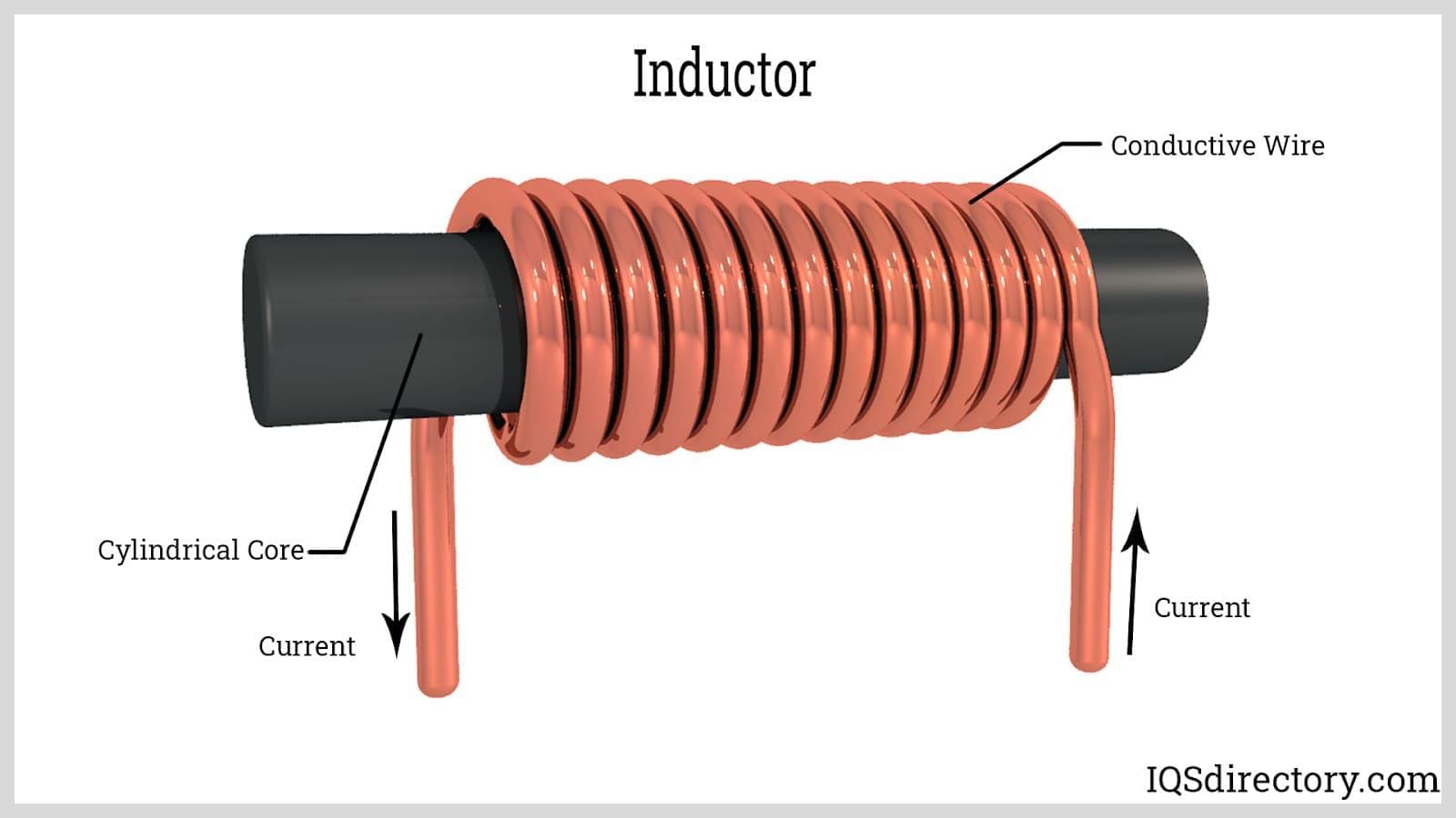
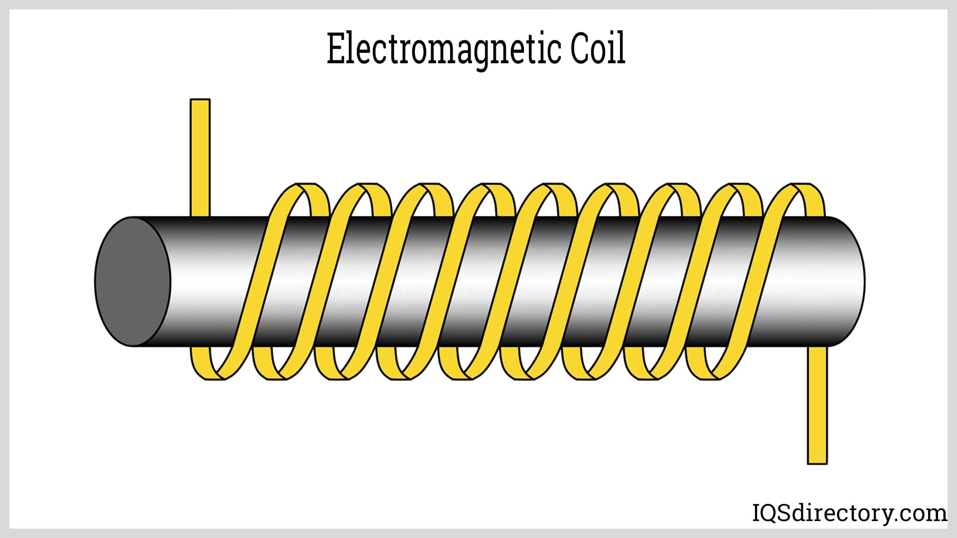
An inductor is a wire coil that stores energy in a magnetic field when fluctuating electric current flows through it. They are categorized by the type of core around which their wires are wound. Inductors are a passive component that take advantage of the relationship between magnetism and electricity as a result of the electric current. The magnetic field of an inductor is far stronger than a magnetic field produced by a simple coiled wire. All wire, when current passes through it, creates a magnetic field. The will planned windings of inductors significantly increase the strength of magnetic fields created by normal wire.
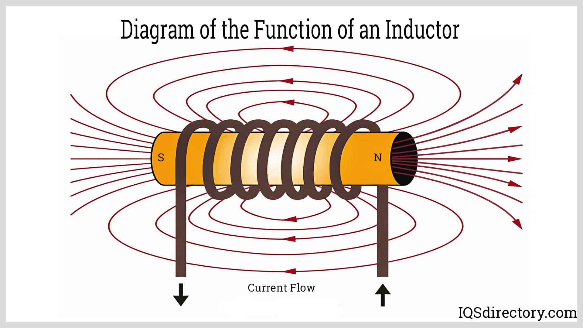
Unlike a capacitor that opposes a change in voltage, an inductor opposes the rate of change in the current flowing through it by building up energy in its magnetic field. This ability that relates current with the magnetic flux linkage or flux density as a constant proportionality is referred to as inductance that is symbolized as L in units of Henry (H), which is the International System of Units (SI) that comes from electrical inductance. An inductance of one Henry generates one volt of potential difference across an inductor.
Chapter 2: Types of Inductors
Inductors are one of the most basic types of electrical components that are used in electrical circuits. They store energy in a magnetic field that induces an electromotive force in the form of voltage to oppose a change in current flow. In radio frequency systems, inductors conduct current and reduce feedback and interference. As simple as they may be, inductors are a crucial part of controlling electrical current flow.
The differentiation between inductors is determined by their type of core, windings, shape, and wires. They can be multilayered, coupled, molded, ceramic, toroidal, or have specialized designs. In addition to structural differences, inductors change in accordance with the application where they are used. Aside from their various forms, there are high frequency inductors, low frequency inductors, power line inductors, and inductors for decoupling and filtering applications.
Based on Core Material
Air Core Inductor
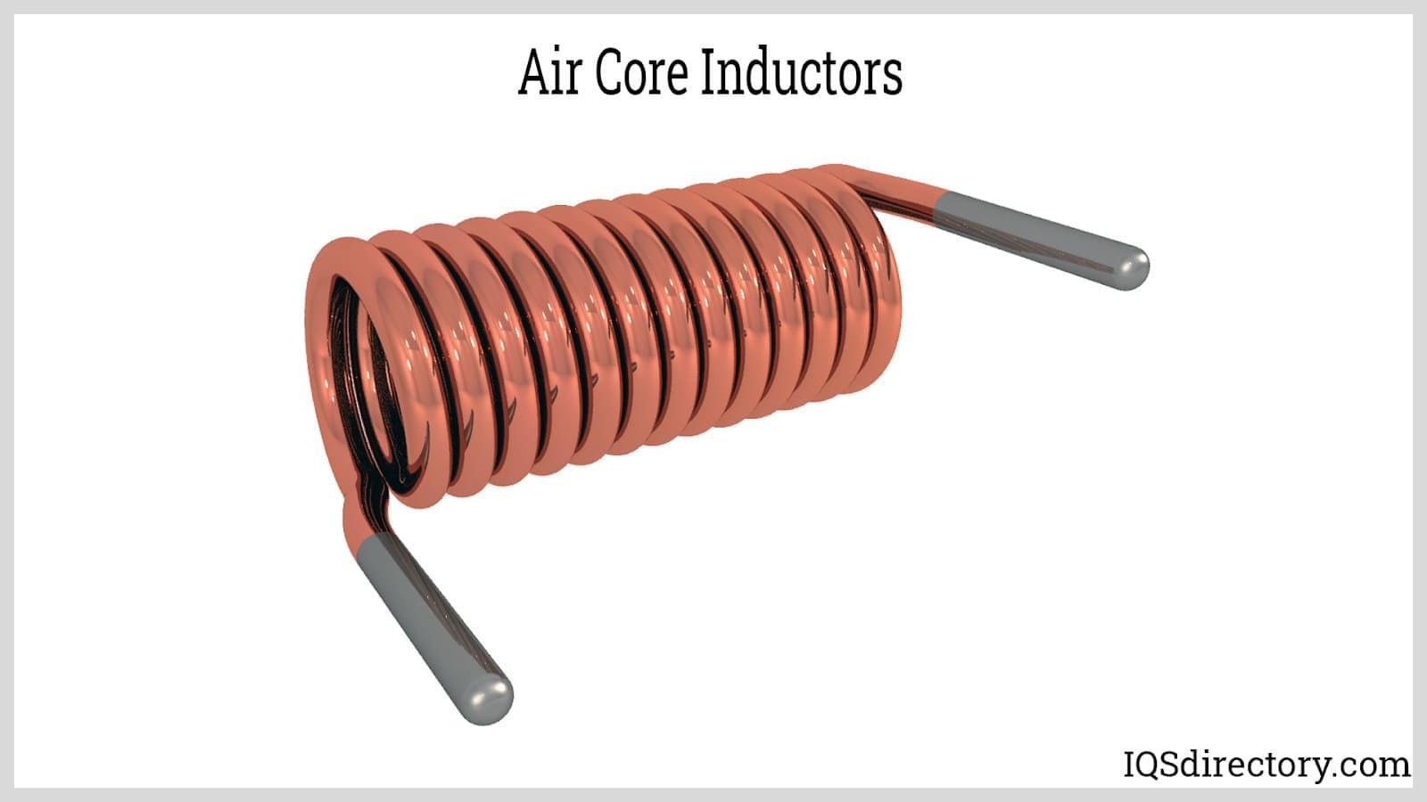
An air core inductor does not have a core but is wired by wire that has been wrapped into the form of a coil. It is a self-supporting inductor that uses air as the method for storing magnetic energy. The leg orientations for an air core inductor are radial, opposed, axial, and special.
The inductance of an air core inductor is dependent on the number of turns of its coil, the diameter of the wires, and the dimensions of the coil. The wires of the coil are made of insulated copper wire with stripped or non-stripped ends. Air core inductors are used due to their inability to experience magnetic saturation, which makes them ideal for high frequency signal applications.
Air core inductors have a lower peak inductance, which decreases any energy loss that is associated with ferrite core inductors. They are used when the amount of inductance needed is less due to the absence of core loss. The low inductance values of an air core inductor make it less susceptible to distortion and enable it to provide greater stability at high frequencies. In order to achieve the low energy loss, air core inductors require more turns compared to other types of inductors.
The amount of inductance (L) by an air core inductor is directly proportional to the square of the number of turns (N) in the coil, the cross-sectional area (A) of the coil, and inversely proportional to the length (l) of the coil, since longer coils have lower inductance.
The choice between an air core inductor and metal core inductor is dependent on the type of application and desired performance characteristics. A metal core allows for a higher level of magnetic permeability and stronger magnetic field, which results in higher inductance. Regardless of the positive attributes of metal core inductors, they can have losses due hysteresis and eddy currents.
Iron Core Inductor
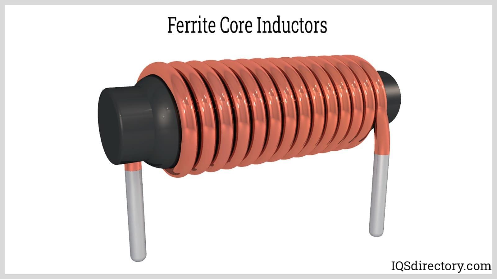
Iron core inductors, also known as ferrite core inductors, are known as fixed value inductors and have high resistance to electricity, high permeability, and low eddy current loss. They have a low inductance value and unique magnetic characteristics that strengthen their magnetic field.
The construction of an iron core inductor includes wrapping insulated wire around an iron core. The conducting material of an iron core helps amplify the magnetic field, which enables it to store magnetic energy. The wires of an iron core inductor are made of nickel iron alloys, magnesium, and cadmium in sizes of 0.014 mm up to 0.056 mm (0.00055 in up to 0.0022 in). The size of the wires varies according to the current levels of an application and the range of frequencies covered by the inductor. The intertwined turns determine the electrical induction when voltage is applied.
The typical design of an iron core inductor includes an iron core or other ferrite material that is wrapped with magnetic circuits to provide the necessary level of inductance. The geometry includes two or more parallel cylindrical partitions that are wound and coated to create a magnetic barrier.
The principle of an iron core inductor is that magnetic induction is proportional to the rate of change of magnetic flux through a circuit. When alternating current (AC) passes through the inductor, the magnetic field of the electricity pushes past the axis resulting in eddy currents in the metal core. The currents create a magnetic field that works against the primary resulting in an opposite magnetic polarity that cancels out voltage from leaks in the wires.
As the number of turns in the inductor increases, the more powerful is its resistance and canceling effects. This process is the reason that huge amounts of electrical power can be fed into an iron core conductor without causing damage.
The presence of the iron core makes these inductors superior at storing magnetic energy because the iron material amplifies the magnetic field. Iron core inductors are used in low frequency applications like audio devices, power supplies, and inverter systems.
Laminated Core Inductor
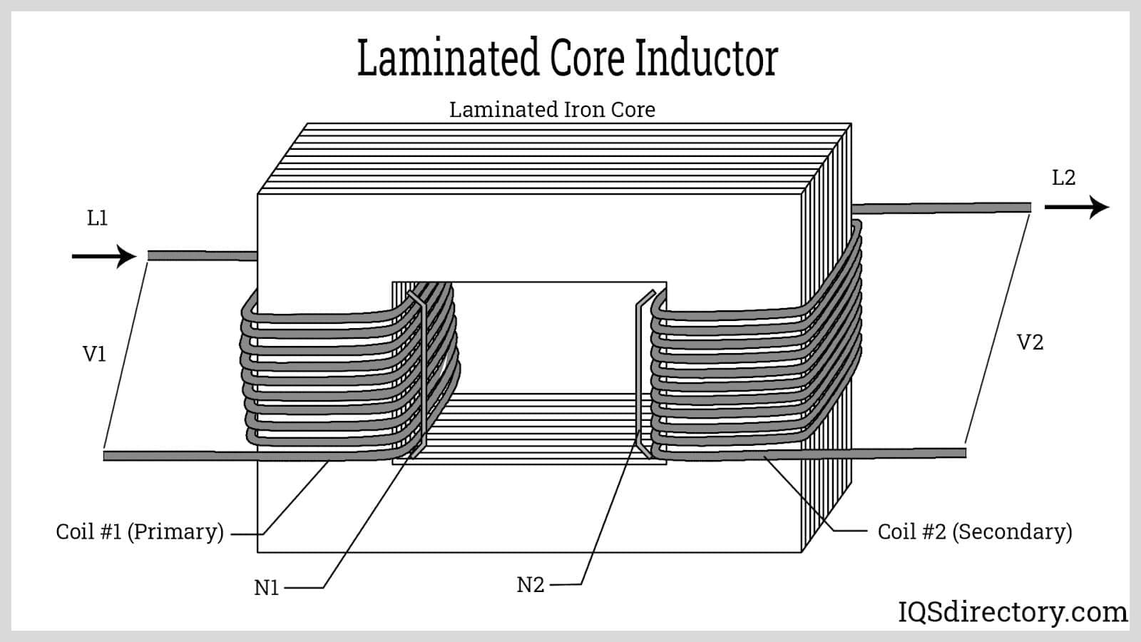
Unlike other types of inductor cores, laminated inductor cores are made of thin sheets of steel or laminations that are stacked together to form the core and placed parallel to the electrical field. Insulation material is placed between the sheets to prevent eddy currents and to keep all currents in the cross sectional area. This construction reduces the looping area and energy loss. They are normally square or rectangular and are smaller than other forms of inductors, which makes them ideal for miniaturized circuits.
The laminations for laminated inductor cores can be made of different types of materials of different thicknesses, a factor that allows for construction flexibility. They are used with high power level applications and with power filtering equipment for the excitation of frequencies.
Undesirable currents that flow in the magnetic field of an inductor are eddy currents that produce heat and inefficiency. With laminated core inductors, the arrangement of the laminates is such that the direction of the flow of the eddy currents is broken by the barriers between the laminates, which includes insulation materials.
Powdered Iron Core Inductor
The unique nature of powdered iron core inductors is in relation to how their cores are produced, which is from pure iron powder that is compressed under high pressure to produce a solid core. The manufacturing process produces a magnetic structure with high saturation flux with the density of iron combined with an air gap core material with a permeability of 100 and high energy storage capabilities.
Powdered iron cores have a variety of configurations including toroidal, E, U, slug, and bus bar with variations in sizes. They are commonly used in power conversion, line filter applications, and radio frequency applications and are substituted for ferrite cores due to ferrite cores having a high permeability and need of an air gap.
The operational temperature range for powder iron cores is between -65°C and 125°C (-85°F and 257°F). At higher temperatures, the binding material for the core decomposes causing degradation. Other factors that cause this phenomenon are the time period, core size, switching frequency, and flux density.
Powder iron cores keep their magnetic properties but do not conduct electricity. Variations in the mixture of the iron powder makes it possible to give the core different permeable characteristics that can range from 200 to 1. By reducing the amount of iron and increasing fillers, an iron powder core acts as if it has gaps sawed into it that are evenly distributed around the core.
Based on Core Design
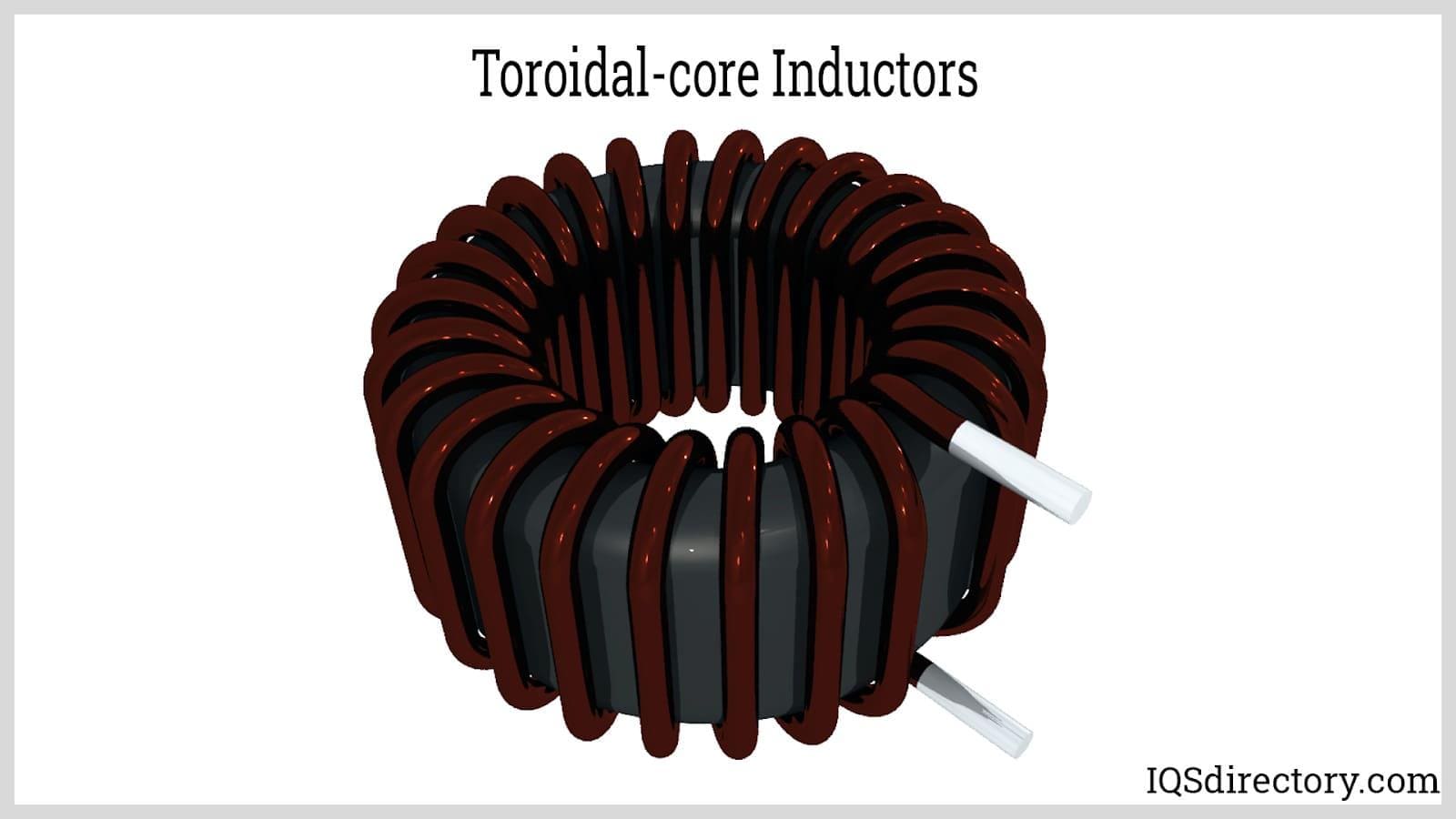
Toroidal Inductor
The key feature that differentiates toroidal inductors from other types of inductors is their shape, which is that of a donut or metal sphere wrapped with wire. The closed loop shape of a toroidal inductor allows it to resist a wide range of frequencies. As with iron core inductors, the donuts of toroidal inductors are made of ferrite metals, iron, powdered iron, and other metals. The geometry of a toroidal inductor leads to nearly complete cancellation of magnetic fields.
There are several different types of toroidal inductors that include standard toroid, SMD power, high temperature, coupled toroid, common mode toroid, low loss, vertical, and current. The various types generate nominal inductance that ranges from 25 µH up to 100 µH.
Toroidal inductors work like any other form of inductor that increase frequencies to a desired level. The strength of the magnetic field depends on the flow of the current value and the number of twists perpendicular to the flow. A unique feature of toroidal inductors is their various coatings, which provide a smooth radius and winding surface. The coatings offer edge coverage, edge protection, and insulation and come in different colors of epoxy paint and parylene coatings.
The cross section of a toroidal inductor core can be round, square, or rectangular with cancellation being more complete with round cross sections due the shorter turn length per cross sectional area and lower winding resistance.
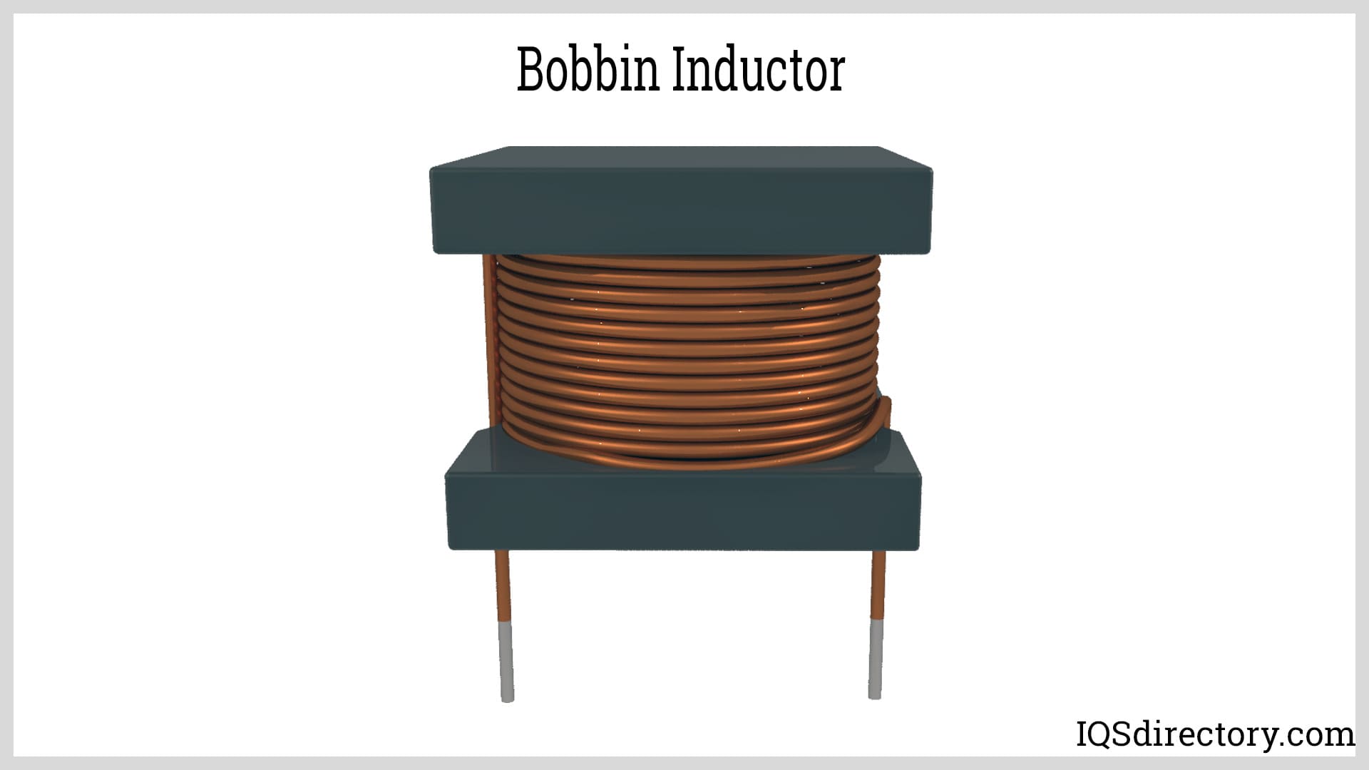
Bobbin Inductor
A bobbin inductor has its coil wound in the form of a bobbin, which is a cylinder with a ridge on the top and bottom to hold wires. The process of manufacturing a bobbin inductor involves connecting the wire to the ridge and turning the bobbin such that the wire is carefully and evenly wound around the cylinder. Similar to an axial inductor, bobbin inductors have two leads that take two different forms. Axial bobbin leads exit the inductor at both ends of the bobbin while radial leads exit the inductor at one end of the inductor and look like forks.
Since bobbin inductors are used in several applications, they are made from a variety of materials including plastics, phenolic, glass, and TeflonTM. The manufacturing process for bobbins varies between molding and fabrication. They come with terminals, pins, and surface mount pads for easy wire terminations and for print circuit board mounting. There is a wide selection of shapes of bobbin wound inductors, which include round, square with pot core, round with slab core, and double slab pot cores with custom shapes also available. The core materials for bobbin inductors are similar to other inductors.
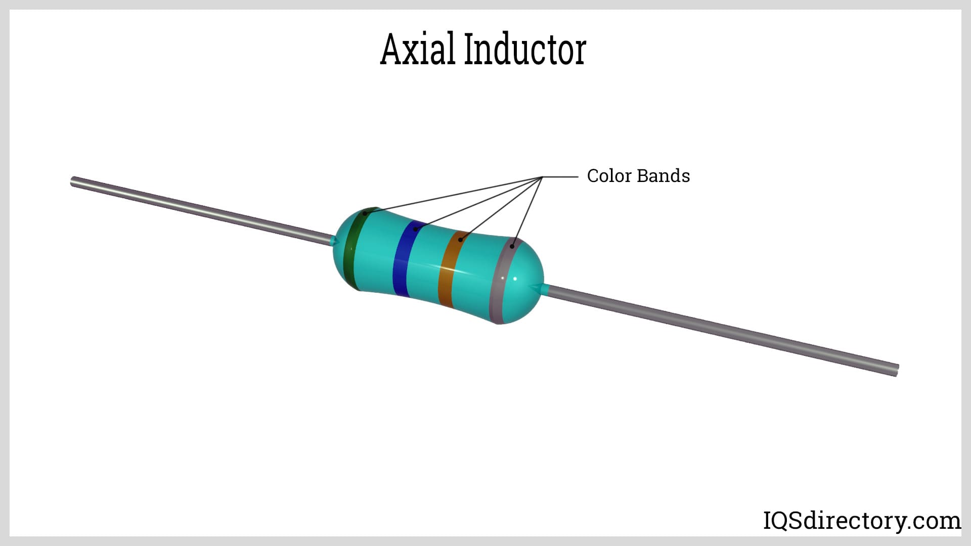
Axial Inductor
Axial inductors are made by wrapping wire around a dumbbell shaped ferrite core with leads connected at the top and bottom of the dumbbell. The assembly of wires, leads, and dumbbell shape are put through a molding process where green material surrounds the inductor and values are printed as colored bands. The value of the inductor can be determined by reading the bands and comparing them to color coded charts.
An axial inductor, also known as a coil, choke, or reactor, is a passive electrical component that stores energy in a magnetic field. They are small inductors for low current and low power applications. Axial inductors are available in several types of core materials including phenolic, ferrite, and iron powder.
Based on Their Usage
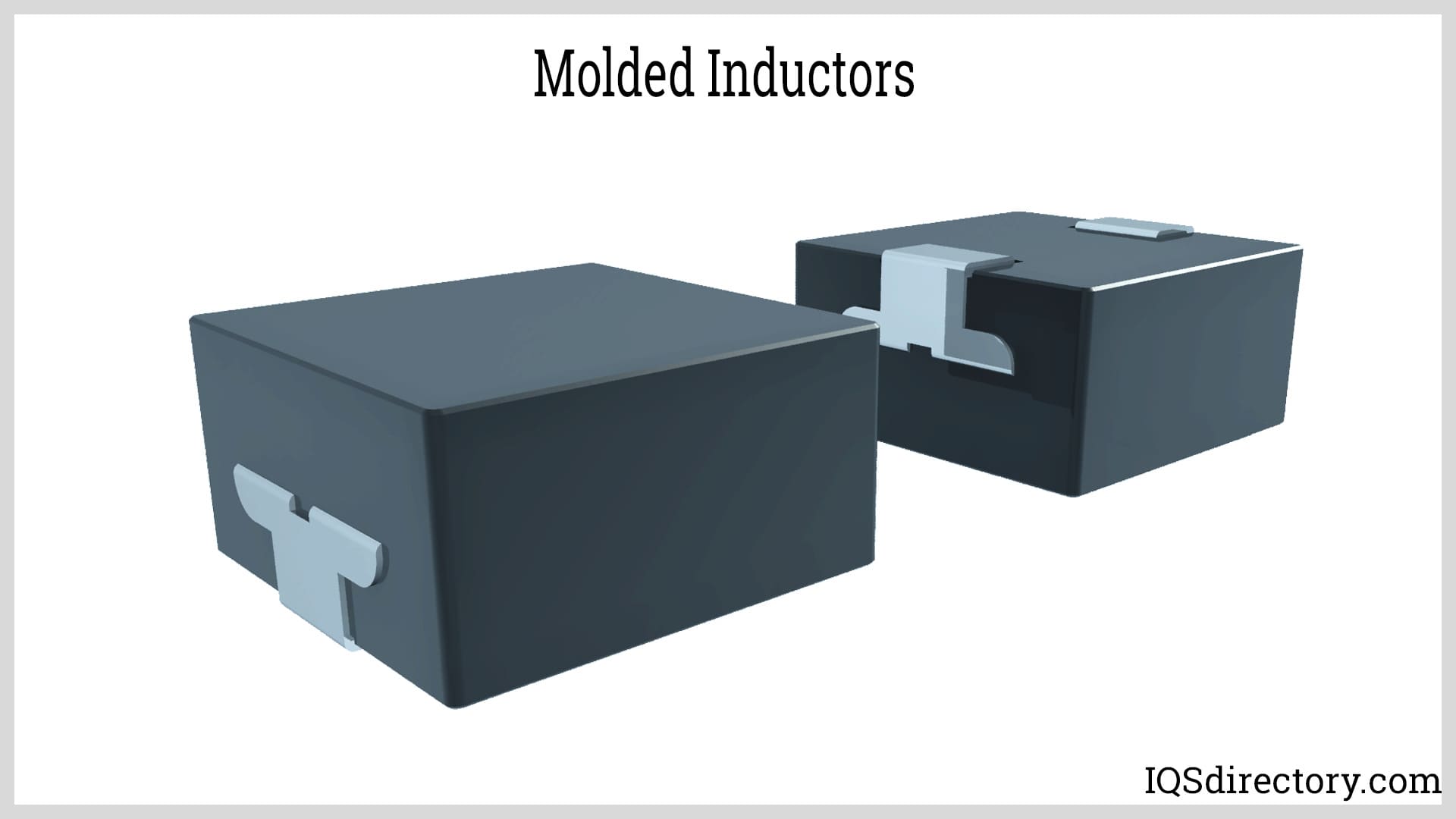
Molded Inductor
Molded inductors are made by compressing magnetic material in a mold around a conducting air coil using a binder or polymer to form the structure. The compressed structure is cured in an oven to form a united composite with the binder acting as a distributed gap. Molded inductors are designed for use with computers and telecommunication equipment. The compressing of the components blocks air and noise and enhances the inductor’s magnetic performance. Inductance is stable across a wide current range and drops above rated currents for power reliability.
Magnetic materials used in the construction of a molded inductor include nickel zinc ferrite, manganese, iron powder, and other metal alloys. Molded inductors are lightweight, small, and low cost with DC bias and saturation current with a frequency range up to 5 MHz.
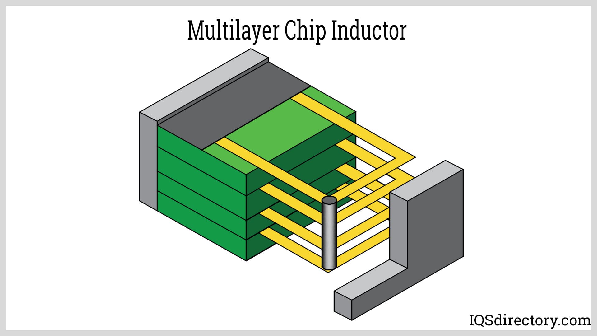
Multilayer Chip Inductor
Multilayer chip inductors have a structure that is similar to laminated inductors in that they have multiple winding layers stacked together and are made by drying and molding ferrite or ceramic paste alternated by printing conductive paste that is laminated and sintered into a single unit structure. As with laminated inductors, multilayer inductors are smaller and used for high density mounting with integrated structures, high reliability, and good heat resistance.
The core structure of a multilayer inductor includes multiple windings stacked together but separated by insulation. Each of the windings in the stack generates a magnetic field from the flow of current. The stacked design intensifies the magnetic induction, which makes it possible for multilayer inductors to store and release energy efficiently.
As with several of the different inductors, the small size of multilayer chip inductors makes them ideal for the miniaturized circuits of modern electronics and use with compact circuit board layouts. For this reason, multilayer inductors are used in communication devices, computer hardware, power management circuits, and filter circuits.
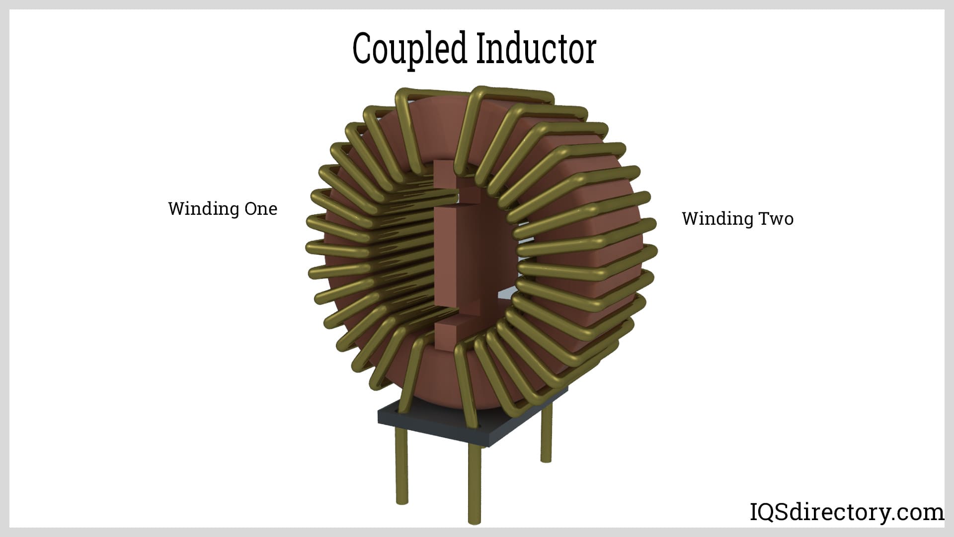
Coupled Inductor
A coupled inductor contains two or more windings with a common core and functions as a DC-DC converter by transferring energy from one winding to the other winding through the common core, which is referred to as mutual inductance. They are used in voltage regulating circuits to provide the required output voltage that may be stepped up or down.
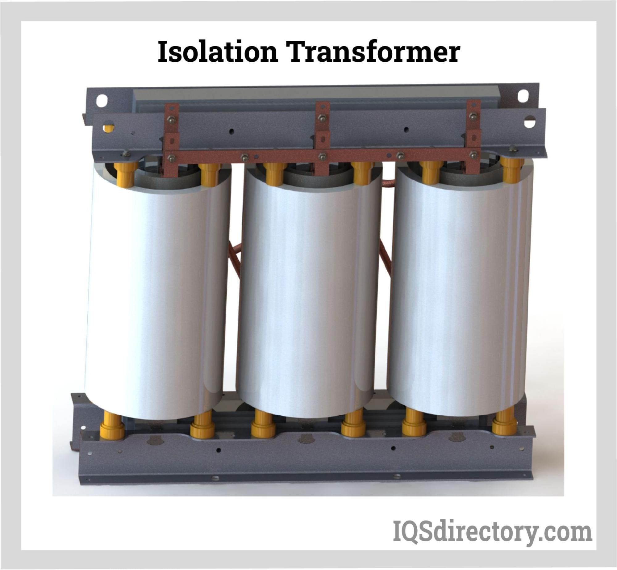
The windings of coupled inductors can be connected separately for use as an isolation transformer. To achieve higher inductance, the windings can be connected in a series and used as a tapped inductor. These two connection methods are a small sample of the many types of connections and uses that have been found for coupled inductors.
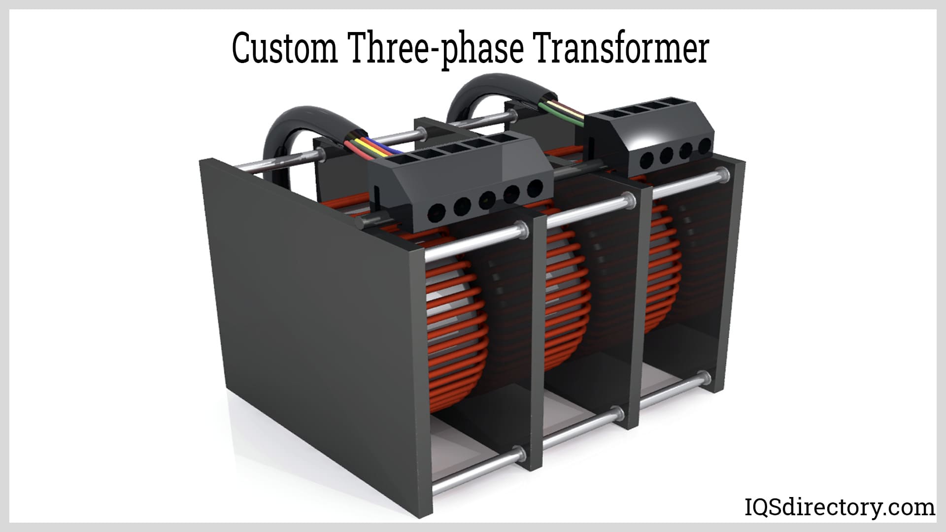
Although there is little difference between a coupled inductor and a transformer since they both use cores to store energy and transfer energy between windings. The key factor is that coupled inductors are designed for specific applications and uses.
The ten inductors described above is a sampling of the many inductors that are provided by manufacturers and does not include the endless number of custom inductors that are produced for special and unique applications. Inductors are an essential part of electrical circuits and serve several functions depending on the design and requirements of a circuit.
Chapter 3: Inductors and Inductance
Inductors are an important part of the flow of electricity and operate when there are sudden changes in the flow. When current is in a steady state, it passes through an inductor as if the inductor is any form of wiring. In that instance, there isn’t any reaction from the inductor.
When there are sudden changes in the current flow or the flow of electrons, the inductor resists the changes. Inductors lag behind changes to current because of their magnetic field, which increases if the current increases or decreases. The changes in the magnetic field causes changes in the magnetic flux, which induces an electromagnetic field (EMF) that opposes changes in the current as the current increases or decreases.
Inductance is the ability of an inductor to resist the changes in current, which is the ratio of voltage to the current’s rate of change within the coil of the inductor. Inductance is measured in Henrys (H), a measurement for a high amount of electrical energy. The measuring of inductance in inductors is in millihenrys (mH), microhenrys (µH), or nanohenries (nH). The factors that influence an inductor's inductance are its number of coils, the length of its wires, the material of the core, and the size and shape of the core. With an air inductor, the radius of the coil influences its inductance.
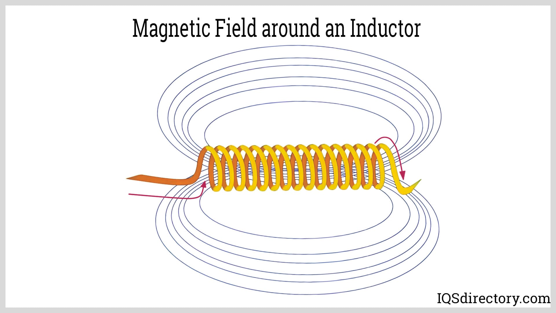
When current flowing through an inductor slows or stops, its magnetic field collapses and induces current flow and energy is released without any change.
Mutual Inductance
Mutual inductance occurs when two coils are placed close together such that the magnetic field of one coil links to the other coil, which leads to the generation of voltage in the second coil. The amount of mutual inductance of the two coils is dependent on the positioning of the coils.
As the distance between the coils decreases, nearly all of the magnetic flux by the first coil will interact with the second coil. As the distance between them increases, the magnetic flux from the first coil to the second coil weakens. The amount of inductance between the coils can be greatly increased by connecting them to a common soft iron core or increasing their number of turns. If the two coils are tightly wound together, unity coupling occurs and losses of leakage flux dramatically diminishes.
Self Inductance
Self inductance is a unique property of current carrying coils that resist any changes in the current flowing through them and is due to a self-induced EMF that is produced by the coil. The EMF resists and is in opposition to any rise in the current or any decrease. It is a phenomenon that does not involve the presence of an inductor.
Chapter 4: Types of Wires Used in an Inductor
Different types of wire are used for various magnetic applications with round wire being the most common. The basic structure of an inductor consists of a coil of conducting material with some form of wire wrapped around a core of ferromagnetic material or coiled without a core. The wires of an inductor are the component that resists or opposes changes in the current.
Round Wire (RWC)
Round wire is the most commonly used type of wire for inductors and is normally covered with a layer of insulation material that includes polyester, polyurethane, and polyester amideimide applied to several different gauges of wire. The wires are wound around a core made of metal, plastic, or ceramics. With air inductors, wires are wound on a mandrel and used without a core.
Flat Wire
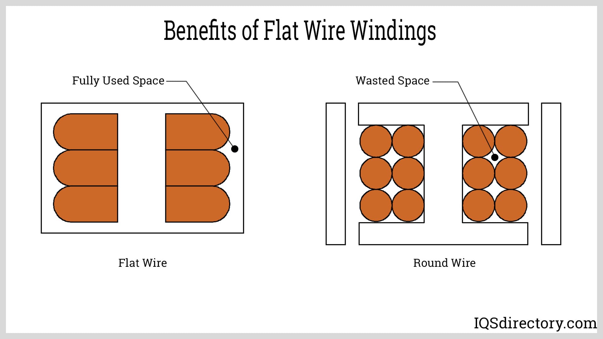
Flat wire is used as a solution to the skin effect, where the current flows near the surface of the conductor without current in the central area. The skin effect leads to higher AC resistance at higher frequencies.
Flat wire, with about 60% more surface, reduces the skin effect at up to 5 MHz and supports higher inductance values and higher currents. They have a 95% winding factor that makes it possible to produce smaller inductors. In round wire windings, the space between the windings can be up to 30%, which is only 5% with flat wires.
To increase the effective density, flat wires are used in molded inductors to eliminate wasted space and increase efficiency in a smaller package.
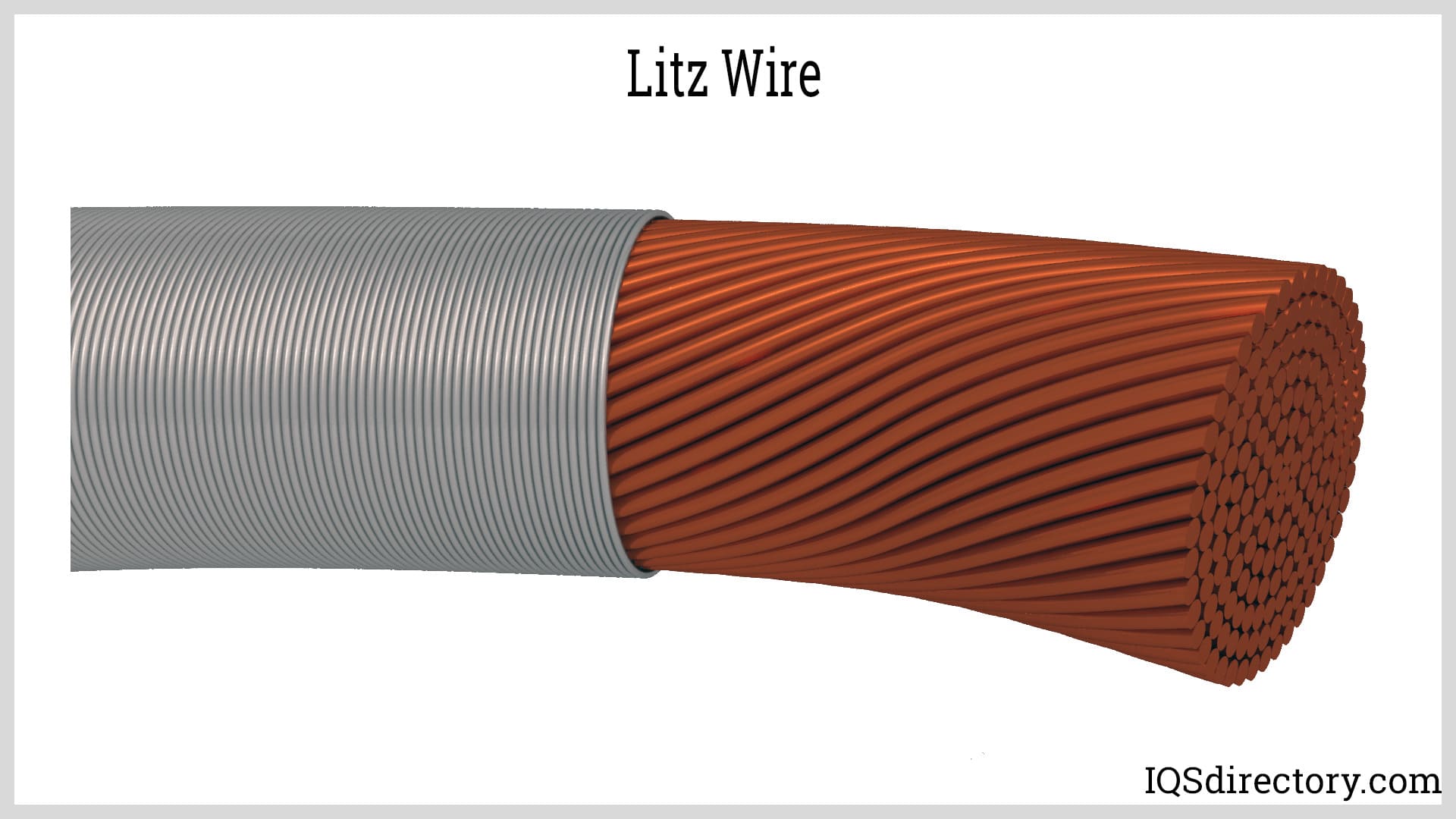
Litz Wire
Litz wire is unlike flat and round wire in that it is made up of several copper wires that are braided or woven together. The proportion of each strand of wire is evenly distributed among the strands to create an operational efficiency that is 100% higher than any form of conventional wire. The types of Litz wire can be round or rectangular with rectangular Litz wire capable of supporting high windings with a significant decrease in skin and proximity effects.
The ease of use and exceptional AC resistance of Litz wire makes it ideal for high frequency transformers. Of the various forms of wire, Litz wire has the lowest inductance leakage. The factor that limits the use of Litz wire is its cost, which is significantly higher than copper wire.
Chapter 5: Unique Inductor Designs
The common configurations of inductors are wires wrapped around a core of air or different types of metals. Over the years, and for various types of applications, inductors have been manufactured that use different forms to perform the same types of functions as those of conventional or traditional inductors. The structure of these different inductors can be similar to the wound wire versions but include variations that are unusual and unique.
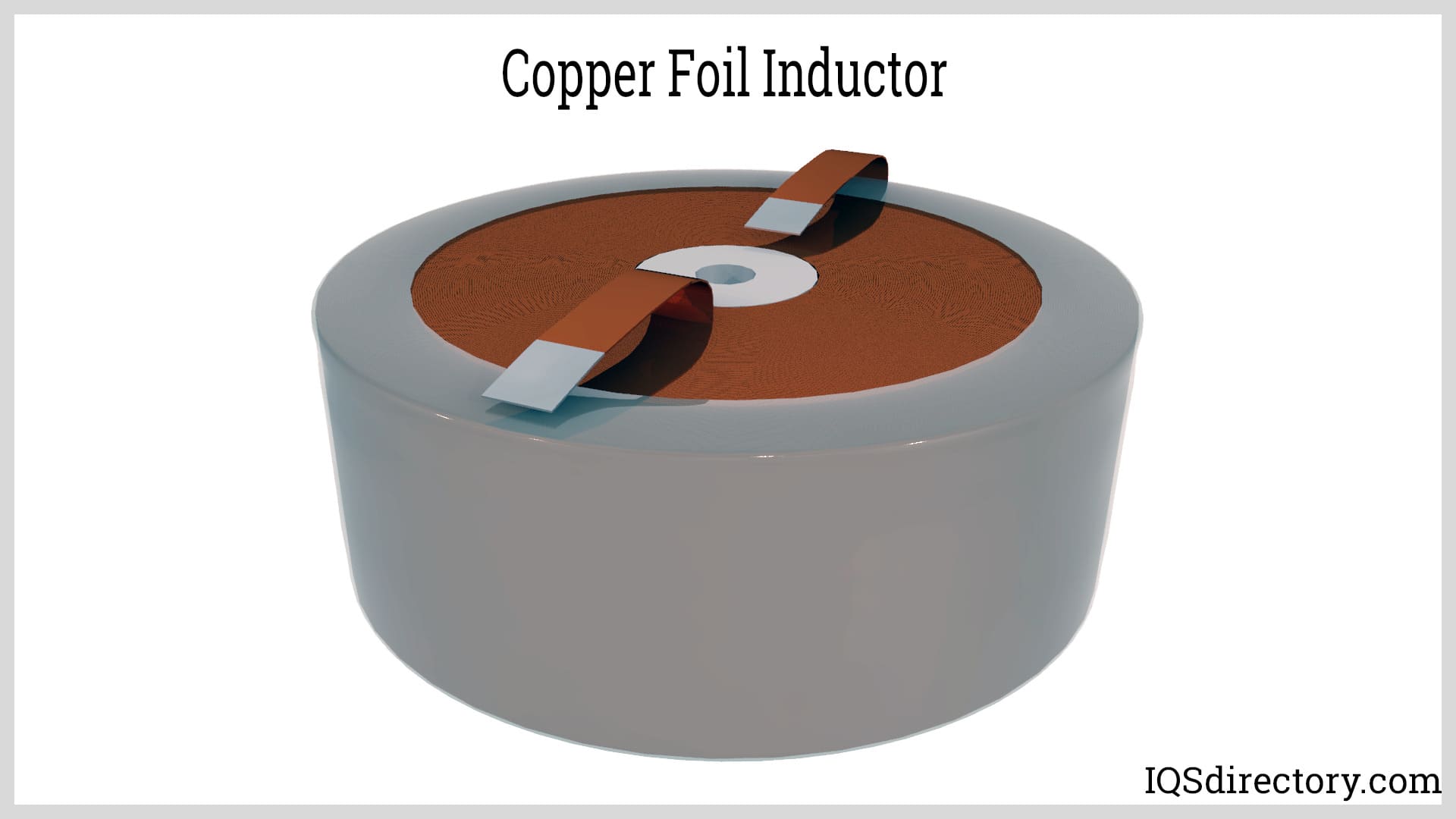
Copper Foil
The structure of copper foil inductors consists of pure copper foil separated by a thin poly film or wax paper. Copper foil inductors have less winding space, better heat dissipation, a reduction of voltage stress between turns, and higher mechanical strength than wire wound inductors. They remain cool during long periods of high-power output due to their higher winding density.
The term copper foil is a generic term used to describe a wide assortment of coppers used to produce copper foil, which include oxygen-free high conductivity copper (CDA 10100), oxygen free high conductivity copper (CDA 10200) and electrolytic tough pitch (ETP) copper (CDA 11000). CDA 10100 and CDA 10200 have the highest purity and are the least expensive. ETP is ideal for commercial applications.
Planar Inductor or Two-Dimensional Inductor
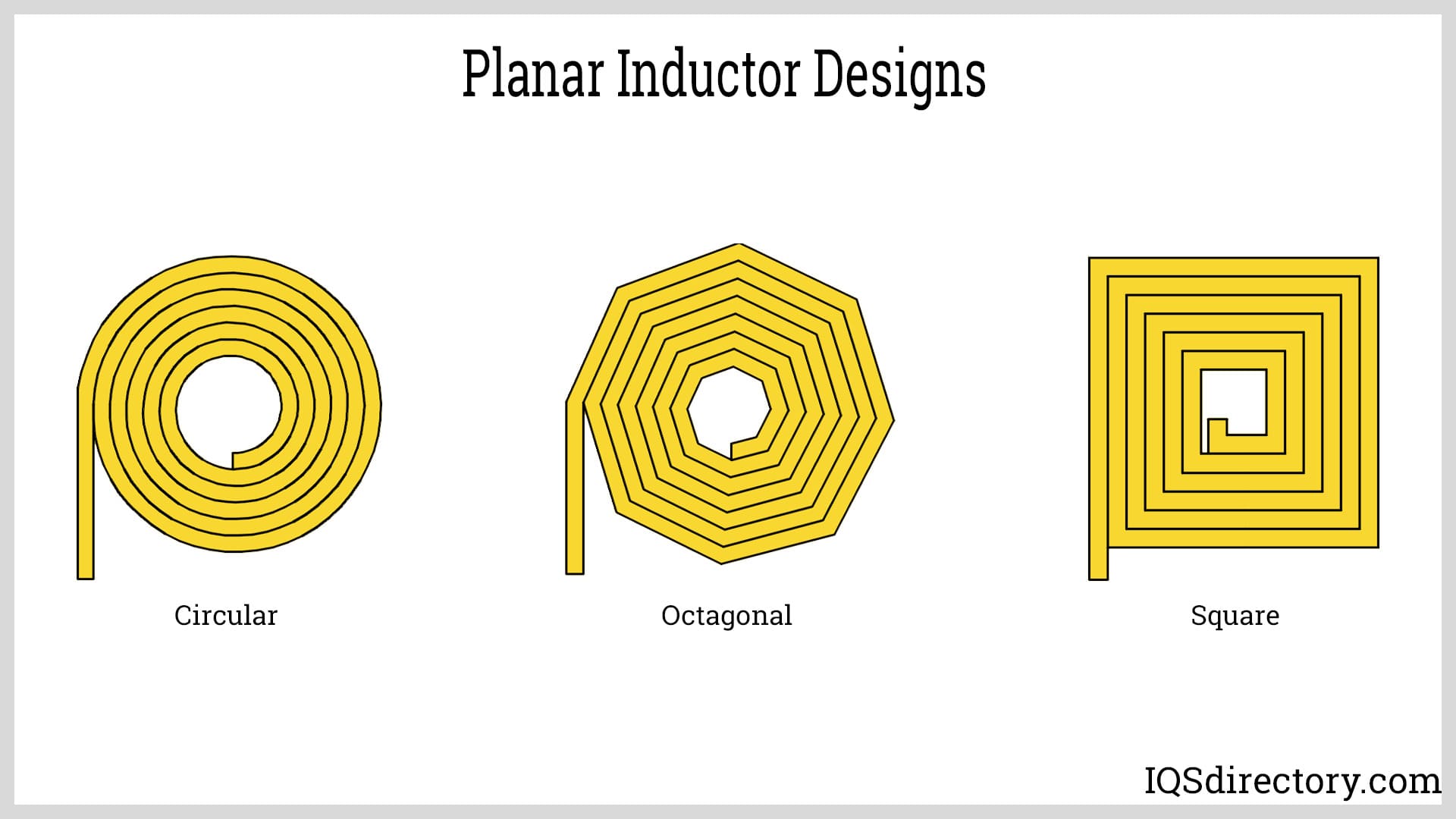
Planar inductors are flat two dimensional inductors that are made in the same way as traditional inductors with a magnetic core and windings. The difference between conventional inductors and planar inductors is the core, which is a planar or plane flat surface with windings in the Z direction that is opposite to helical x y windings. The windings of planar inductors are low profile with low leakage and reduced AC resistance that reduces losses.
As with copper foil and flat wire windings, the larger surface area of planar windings improves temperature characteristics. The inductance value of a planar inductor using PCB technology depends on the number of turns, width, separation, and inner and outer windings. Their design can be circular, rectangular, square, hexagonal, or octagonal. The various designs economically increase power density and inductor performance.
The increasing use of planar two-dimensional inductors is due to their low profile, high efficiency, and compact physical size. They have the same flexibility as conventional inducers with a wider array of inductor winding designs.
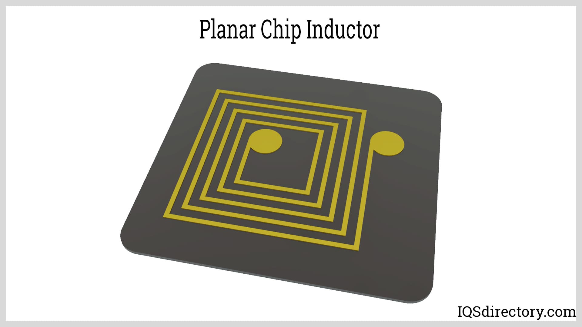
Special forms of planar inductors are printed on a PCB using layers to provide a low-profile magnetic field. Flat copper sheets or etched spiral patterns are used to form the windings to replace the turns of wires. The chip form of planar inductor is thin and ideal for low profile applications or when several circuit boards are stacked
Chapter 6: Inductor Symbols
Different symbols are used to identify different types of inductors when represented in a circuit diagram. All inductors are indicated by the symbol of a single spiraling wire while transformers are represented by the image of two spiraling wires.
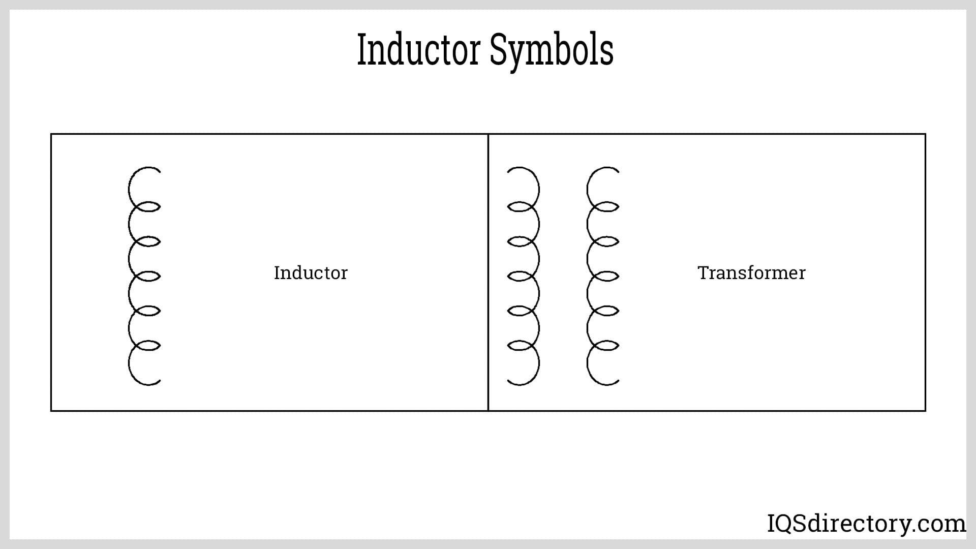
Inductor symbols are as visual shorthand for providing information about an inductor’s properties and characteristics. Variations are included in the symbol to indicate core materials, polarity, tapped coil, or mutual inductance. Aside from the symbol, an inductor symbol is identified by the letter “L” to show its presence in a circuit.
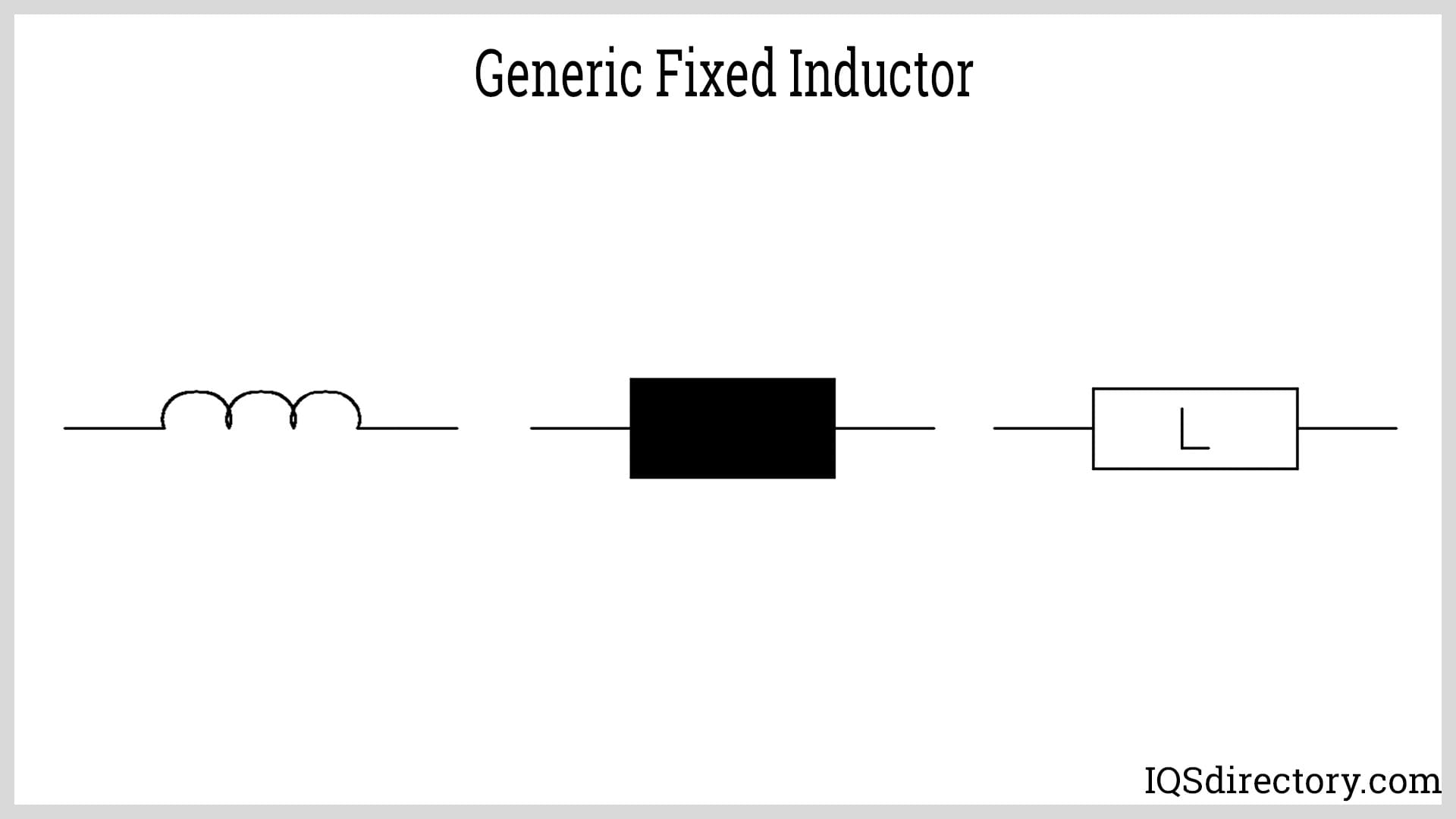
Generic fixed inductor symbols represent inductors that have a fixed inductance and are known as coils or chokes that store magnetic energy.
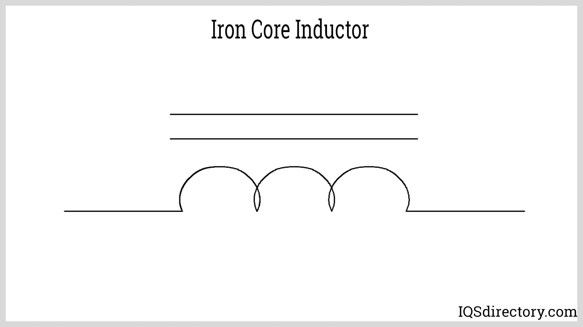
Iron core inductors made of ferromagnetic material have increased inductance due their high permeability.
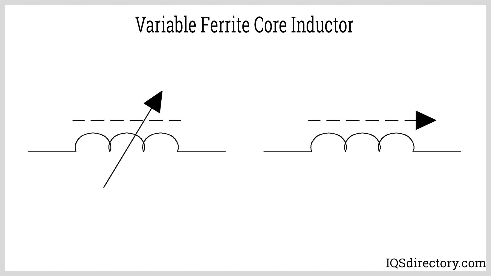
Variable ferrite core inductors have variable inductance that can be changed by screwing in or screwing out the core inside the coil.
The few symbols here are a small sampling of the hundreds of symbols that are used in circuit diagrams to represent inductors. The various types of symbols provide valuable information to DIY enthusiasts, engineers, designers, and electricians. They are a part of the unique language associated with electronics, electrical circuits, and electrical currents.
Chapter 7: Factors that Affect Inductance
There are four factors that determine the amount of inductance that can be created by an inductor. These factors dictate inductance by affecting the amount of magnetic flux that develops and the amount of force of the magnetic field. Inductance is the scale of an electrical component to induce an electromotive force that is caused by a variation in electrical current. It is quantified by the cross-sectional area of a coil, the number of wire turns, permeability, and the length of the coil and is measured in Henrys (H).
Inductance is the result of the magnetic field due to the current per the turns in an inductor’s coil. The parameters of electronic components determine their performance and how they will be used. The various parameters offer the necessary knowledge of how and in what type of circuit an electrical component can or should be used. The parameters for inductors include DC resistance, saturation current, rated current, core permeability, self-capacitance, and self resonant frequency.
Factors that affect the inductance of an inductor relate to its magnetic field and the turns of its coil.
Length of the Coil
Inductance is dramatically influenced by the length of an inductor’s coil, which is made of conducting material wrapped around a core that increases the magnetic field of the inductor and keeps the magnetic field close to the inductor, a factor that increases inductance. As the coil of an inductor gets longer, its inductance becomes less. In contrast, shorter coils have higher inductance.
When the magnetic field flux gets longer, it requires more opposition to the formation of the flux for any given field force.
Core Materials
The magnetic permeability of the core of an inductor increases its inductance. In this case, permeability is the amount of magnetization of a core in response to a magnetic field. Since the core of an inductor stores recoverable energy, it is essential that it has high permeability. Greater permeability results in a greater magnetic field flux for a given amount of field force. Most cores are made of steel, iron, manganese, or powdered metals.
Coil Area
Unlike the length of an inductor’s coil where a shorter coil means more inductance, greater coil area results in more inductance. As the coil area increases, there is less opposition to the creation of magnetic field flux. The inductance of an inductor increases as the cross sectional area of the core increases. By doubling the radius of a coil, inductance increases by a factor of four.
Coil Wire Turns
The number of turns in coils play a significant factor in the efficiency of various electrical devices. As with all electronics, inductors and their inductance is affected by the turns of the wire that make up the coil. As the number of turns increases, the inductance in an inductor gets greater. The increase in wire turns is related to the area of the coil. The more turns means a coil can generate a higher magnetic field force that is measured in AMPs per turn.
Conclusion
- Inductors are a passive component that take advantage of the relationship between magnetism and electricity as a result of the electric current.
- Unlike a capacitor that opposes a change in voltage, an inductor opposes the rate of change in the current flowing through by the buildup of energy in its magnetic field.
- Inductors are one of the most basic types of electrical components that are used in electrical circuits. They store energy in a magnetic field that induces an electromotive force in the form of voltage to oppose a change in current flow.
- Inductors are an important part of the flow of electricity and operate when there are sudden changes in the flow. When current is in a steady state, it passes through an inductor as if the inductor is any form of wiring. In that instance, there isn’t any reaction from the inductor.
- Over the years, and for various types of applications, inductors have been manufactured that use different forms to perform the same types of functions as those of conventional or traditional inductors.




 Electric Coils
 Electric Switches
 Electric Transformers
 Electronic Connectors
 Electronic Enclosures
 EMI Shielding
 Membrane Switches
 Power Cords
 Static Eliminators
 Castings & Forgings
 Bulk Material Handling
 Electrical & Electronic Components
 Flow Instrumentation
 Hardware
 Material Handling Equipment
 Metal Cutting Services
 Metal Forming Services
 Metal Suppliers
 Motion Control Products
 Plant & Facility Equipment
 Plant & Facility Supplies
 Plastic Molding Processes
 Pumps & Valves
 Recycling Equipment
 Rubber Products & Services